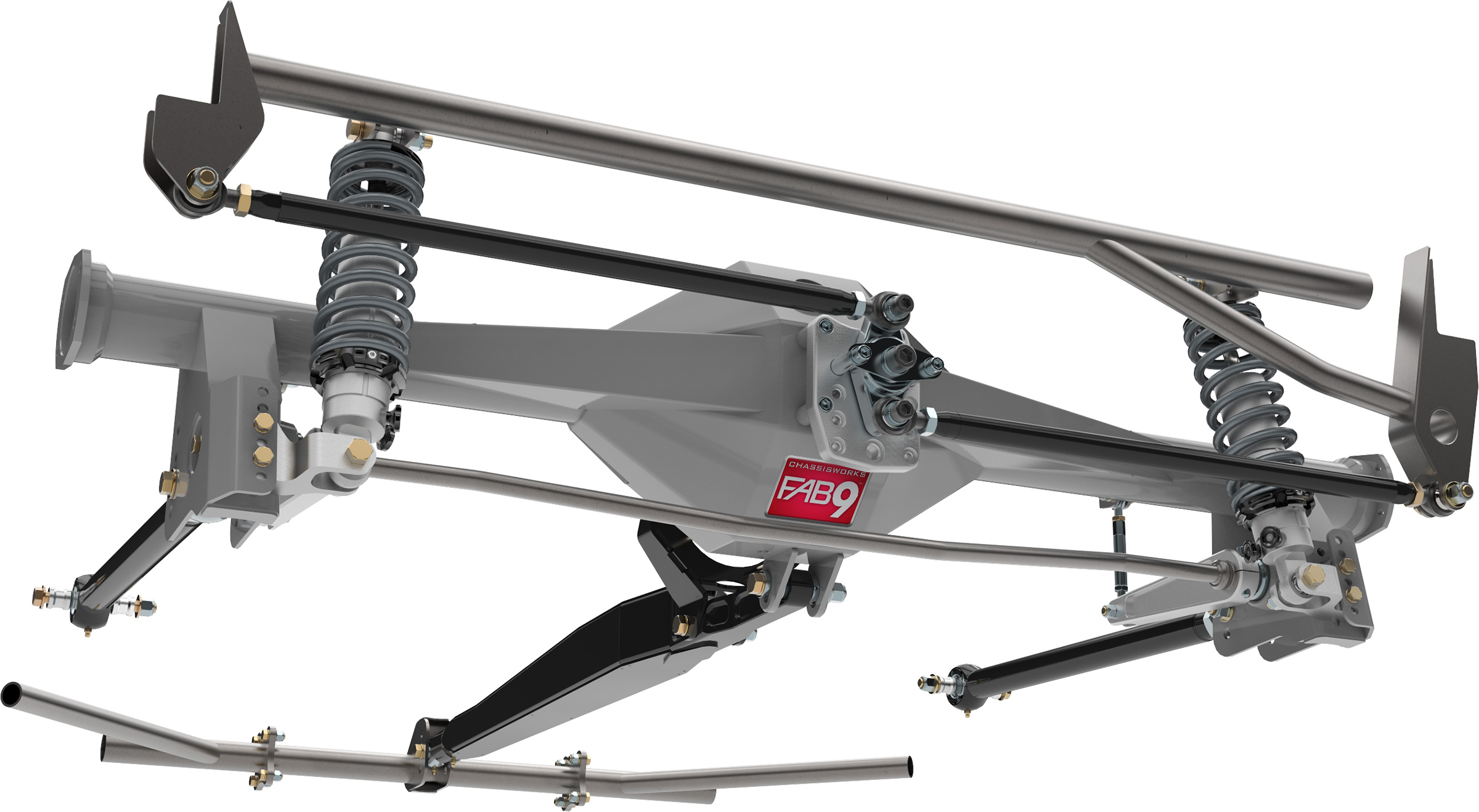
Anyone heard of these guys?
https://www.nextventuremotorsports.com/ ... -tjljxjmj/
Looks like nice parts!
Quarantine Project - YJ Unlimited Stretch
-
Eric

- Posts: 892
- Joined: Thu Aug 09, 2001 11:00 am
- Location: Gilpin County
-
YJLopes
- Posts: 442
- Joined: Sun Feb 10, 2002 5:00 pm
- Location: Aurora, CO
Drop me a line when you are stopping in to Front Range and I'll show you around our shop!Eric wrote:Your project is looking greatNice work. BTW I've visited the "space port" a few times now but no full stops. Most recently for IFR training but that's on hold for a bit of course.
Today was spent cleaning up the windshield frame. I had to trim the corners to fit the LJ top. Here I have marked it for the initial cut I did 3 weeks ago.

I don't know what happened to the pics I had of it after the cut, but it was ugly. Several layers of sheetmetal all pressed together at the edges and spot welded. Today I cleaned it up a bit with the flap disc and started tacking it back to a smooth edge. The first pass looked like this, I suppose because there were so many impurities in the weld that I couldn't clean out with the grinder.

I ground that smooth and then tacked in all the holes and ground that and on and on for about 15 minutes on each side to get this.


Once I was happy with that, I had to remove the double-sided tape that was on the new gasket because it was sticking so far out in front of the windshield frame that it wasn't going to stick to anything.

Scraping that off ate up 30 minutes. The gasket has fits over the top edge of the windshield frame pretty snug, so I think I'll just let that hold it in place for now. If I need to add some weatherstrip adhesive down the road I can do that.
After that was all done I was hunting for things to do while I'm waiting for parts. I need to do a bit of welding to the center section of the the rear axle, and when I was playing with the drive flange the pinion felt a little loose, so I decided it was as good a time as any to strip down the axle and give it a once over. I found that the pinion nut was a hair loose and the pinion bearings could probably stand to be replaced. On the plus side, the repair I did in this thread http://www.colorado4x4.org/vbb/showthre ... ight=ected seems to be holding up.
Tomorrow the USPS is supposed to bring me the parts to weld to the center section. Tuesday or wednesday I should see my Johnny joints and brackets. With any luck I hope to have a roller by the end of the week.
-
YJLopes
- Posts: 442
- Joined: Sun Feb 10, 2002 5:00 pm
- Location: Aurora, CO
Brown santa has had me waiting for parts all week. Still waiting on 2# of NI55 welding wire, a summit order, and bump stops form 4WP.
In the mean time I cut some bushings to use as dummy spacers for welding together the brackets so I didn't have to worry about the high dollar joints getting spattered. Here are the Barnes 3 link brackets that I am using for LCA brackets going together.


Here is the LH UCA bracket with a bushing in it and the track bar the way that Artec wants you to put it together.


Since I am pushing the axle back I wanted to relocate the track bar forward a bit. I cut up the back half of the artec bracket and made it fit in front. I can do this because I won't have any upper control arms. I used another bushing that a made to get this spacing right.


Everything is tacked on the truss, so I decided to mock it up and see how everything fit. The torque arm is the only suspension link that is missing at this point, but hopefully I'll get it in there in the next few days.

I love the bend in the LCAs, gets them up high out of the way.

The track bar looks all kinds of wonky in this pic but it actually is reasonably flat.

Hopefully get the rest of the stuff I need to fab the torque arm by the weekend. In the meantime I hope to fine tune the fit of the LCA brackets tomorrow. They landed right where the frame bends inboard, so I need to make them fit in that corner a bit better.
In the mean time I cut some bushings to use as dummy spacers for welding together the brackets so I didn't have to worry about the high dollar joints getting spattered. Here are the Barnes 3 link brackets that I am using for LCA brackets going together.
Here is the LH UCA bracket with a bushing in it and the track bar the way that Artec wants you to put it together.
Since I am pushing the axle back I wanted to relocate the track bar forward a bit. I cut up the back half of the artec bracket and made it fit in front. I can do this because I won't have any upper control arms. I used another bushing that a made to get this spacing right.
Everything is tacked on the truss, so I decided to mock it up and see how everything fit. The torque arm is the only suspension link that is missing at this point, but hopefully I'll get it in there in the next few days.
I love the bend in the LCAs, gets them up high out of the way.
The track bar looks all kinds of wonky in this pic but it actually is reasonably flat.
Hopefully get the rest of the stuff I need to fab the torque arm by the weekend. In the meantime I hope to fine tune the fit of the LCA brackets tomorrow. They landed right where the frame bends inboard, so I need to make them fit in that corner a bit better.
-
74BuckinBronc

- Posts: 3085
- Joined: Wed Nov 07, 2001 5:00 pm
- Location: NoDak
- Contact:
The pics are at full bump? I assume then your UCA's will be meeting the LCA's in the area of the bend? Very similar design to how I did my bronco, except your arms are longer and bent.
God Forgives, Rock's Don't www.ucora.org
1973 Bronco, 351 SEFI, Locked, discs, 35's ZF-5spd and Atlas 4spd. 235:1 Crawl Ratio
1973 Bronco, 351 SEFI, Locked, discs, 35's ZF-5spd and Atlas 4spd. 235:1 Crawl Ratio
-
YJLopes
- Posts: 442
- Joined: Sun Feb 10, 2002 5:00 pm
- Location: Aurora, CO
The pic is pretty close to ride height. Should have 3.5-4" up travel. I have 12" bilsteins right now, but may have room for 14s. Not sure I need them though.74BuckinBronc wrote:The pics are at full bump? I assume then your UCA's will be meeting the LCA's in the area of the bend? Very similar design to how I did my bronco, except your arms are longer and bent.
No UCAs at all. Pinion lifting will be controlled by a torque arm, kind of like F-body Camaros. The LCA control axle location front ant rear and track bar laterally.
It's a pretty interesting system. Mine is copy of Nth Degree/AEV TJ long arms and will use a lot of their parts. I spent a lot of time talking to the designer of this system years ago when I wrote for Rockcrawler. The goal is better driving ON and off road.
-
74BuckinBronc
- Posts: 3085
- Joined: Wed Nov 07, 2001 5:00 pm
- Location: NoDak
- Contact:
I wasn't sure what you meant by Torque arm, so I was just waiting for it to materialize so I could see what you meant.
God Forgives, Rock's Don't www.ucora.org
1973 Bronco, 351 SEFI, Locked, discs, 35's ZF-5spd and Atlas 4spd. 235:1 Crawl Ratio
1973 Bronco, 351 SEFI, Locked, discs, 35's ZF-5spd and Atlas 4spd. 235:1 Crawl Ratio

-
74BuckinBronc
- Posts: 3085
- Joined: Wed Nov 07, 2001 5:00 pm
- Location: NoDak
- Contact:
That looks interesting! Can't wait to see how you put it together!
God Forgives, Rock's Don't www.ucora.org
1973 Bronco, 351 SEFI, Locked, discs, 35's ZF-5spd and Atlas 4spd. 235:1 Crawl Ratio
1973 Bronco, 351 SEFI, Locked, discs, 35's ZF-5spd and Atlas 4spd. 235:1 Crawl Ratio
-
YJLopes
- Posts: 442
- Joined: Sun Feb 10, 2002 5:00 pm
- Location: Aurora, CO
One of the problems I had to deal with was attaching the torque arm to the center section of the diff. The 8.8 swap has gotten pretty popular amongst the drag racing crowd and the F-body Camaros happen to use a torque arm. There are a few options for installing a torque arm but the only one that doesn't compromise ground clearance is the Hiltsy mount. It shows up in a small USPS flat rate box and you have to weld it together before putting it on the diff.
Here it is partially assembled sitting on my axle.

And another pic of it being assembled and fitted.

The way it fits covers up the fill plug on the axle, so you need to relocate it. I have an ARB cover with drain and fill plugs so that's handled. You need to grind the rib/plug for the Hiltsy mount to clear like this.


Hiltsy is pretty adamant about using NI55 wire to weld the mount to the diff. I've welded to cast before with plain old ER70 but never anything that would take this load so I ordered 2# for $73 and started preheating. I also stole the 100% argon tank from my TIG. Most guys you read about just use a torch and maybe an IR thermometer. Since I was welding over such a large area on the diff and I'm a control freak, I wanted a little finer control. Here is my method.

I set the propane heater close and let it set for 30-40 minutes. It's amazing how much material there is and how long it takes to soak up the heat. Once I'd reached 300ish I started welding. I only welded an inch or 2 and then moved to another location. Once I had a few spots welded I put the heat back on it for 3-5 minutes to put some heat back in it. I'd weld another couple inches here and there and then put the heat back. I repeated this until the mount was welded and the tubes were welded to the center section. After everything was done IO put the heat back on it. After 10 minutes or so I moved the heater away 3-6". I repeated the process of moving the heater 3-6" further away every 10-20 minutes until the majority of the material was down to 100-120 degrees and then shut down the heat. It took about 60-75 minutes IIRC.
I thought I had pics of the TA mount all welded on the axle, but I guess I was so excited that it seemed to be done that I must have forgotten.
I bolted it all back in and started cycling the suspension. The frame side LCA mounts are clamped in place and the torque arm crossmember is very temporary, but it allowed me to see how everything would fit throughout the travel.
Full stuff

Flexing


I did have little interference with the bend in the control arm hitting the frame during flex on both sides. I moved the axle side LCA mounts inboard around 1 5/16" and they clear by 1/2-5/8" now. I think that will be adequate.
Full droop

Once I was satisfied with the fit of everything. I started to do the final weld on the Artec Truss. To avoid causing problems warping the axle, I'd weld a little on ons side, then the opposite side, then wait for it to cool a bit, and repeat. That took a while but while I was waiting I cleaned up the frame where the LCA mounts will weld and prepped the LCA mounts as well.


Still waiting on a summit order for a proper TA mount to bolt to the axle mount I welded on. I hope to have most of the rest of the suspension in place in the next day or 2.
Here it is partially assembled sitting on my axle.
And another pic of it being assembled and fitted.
The way it fits covers up the fill plug on the axle, so you need to relocate it. I have an ARB cover with drain and fill plugs so that's handled. You need to grind the rib/plug for the Hiltsy mount to clear like this.
Hiltsy is pretty adamant about using NI55 wire to weld the mount to the diff. I've welded to cast before with plain old ER70 but never anything that would take this load so I ordered 2# for $73 and started preheating. I also stole the 100% argon tank from my TIG. Most guys you read about just use a torch and maybe an IR thermometer. Since I was welding over such a large area on the diff and I'm a control freak, I wanted a little finer control. Here is my method.
I set the propane heater close and let it set for 30-40 minutes. It's amazing how much material there is and how long it takes to soak up the heat. Once I'd reached 300ish I started welding. I only welded an inch or 2 and then moved to another location. Once I had a few spots welded I put the heat back on it for 3-5 minutes to put some heat back in it. I'd weld another couple inches here and there and then put the heat back. I repeated this until the mount was welded and the tubes were welded to the center section. After everything was done IO put the heat back on it. After 10 minutes or so I moved the heater away 3-6". I repeated the process of moving the heater 3-6" further away every 10-20 minutes until the majority of the material was down to 100-120 degrees and then shut down the heat. It took about 60-75 minutes IIRC.
I thought I had pics of the TA mount all welded on the axle, but I guess I was so excited that it seemed to be done that I must have forgotten.
I bolted it all back in and started cycling the suspension. The frame side LCA mounts are clamped in place and the torque arm crossmember is very temporary, but it allowed me to see how everything would fit throughout the travel.
Full stuff
Flexing
I did have little interference with the bend in the control arm hitting the frame during flex on both sides. I moved the axle side LCA mounts inboard around 1 5/16" and they clear by 1/2-5/8" now. I think that will be adequate.
Full droop
Once I was satisfied with the fit of everything. I started to do the final weld on the Artec Truss. To avoid causing problems warping the axle, I'd weld a little on ons side, then the opposite side, then wait for it to cool a bit, and repeat. That took a while but while I was waiting I cleaned up the frame where the LCA mounts will weld and prepped the LCA mounts as well.
Still waiting on a summit order for a proper TA mount to bolt to the axle mount I welded on. I hope to have most of the rest of the suspension in place in the next day or 2.
-
newracer

- Posts: 2589
- Joined: Mon Aug 07, 2006 10:47 pm
- Location: Timnath, CO
-
74BuckinBronc
- Posts: 3085
- Joined: Wed Nov 07, 2001 5:00 pm
- Location: NoDak
- Contact:
I am still trying to wrap my head around the torque arm. I was surprised to see what looks like an axle anti-wrap bar in there. I thought the setup required an arm going to each side of the frame from the center of the axle?
Very interesting for sure!
Very interesting for sure!
God Forgives, Rock's Don't www.ucora.org
1973 Bronco, 351 SEFI, Locked, discs, 35's ZF-5spd and Atlas 4spd. 235:1 Crawl Ratio
1973 Bronco, 351 SEFI, Locked, discs, 35's ZF-5spd and Atlas 4spd. 235:1 Crawl Ratio
-
YJLopes
- Posts: 442
- Joined: Sun Feb 10, 2002 5:00 pm
- Location: Aurora, CO
Exactly like an anti-wrap bar!74BuckinBronc wrote:I am still trying to wrap my head around the torque arm. I was surprised to see what looks like an axle anti-wrap bar in there. I thought the setup required an arm going to each side of the frame from the center of the axle?
Very interesting for sure!
-
newracer
- Posts: 2589
- Joined: Mon Aug 07, 2006 10:47 pm
- Location: Timnath, CO
-
YJLopes
- Posts: 442
- Joined: Sun Feb 10, 2002 5:00 pm
- Location: Aurora, CO

-
74BuckinBronc
- Posts: 3085
- Joined: Wed Nov 07, 2001 5:00 pm
- Location: NoDak
- Contact:
LOL - that muddy's the waters for me. I am not seeing anything that controls body roll.
God Forgives, Rock's Don't www.ucora.org
1973 Bronco, 351 SEFI, Locked, discs, 35's ZF-5spd and Atlas 4spd. 235:1 Crawl Ratio
1973 Bronco, 351 SEFI, Locked, discs, 35's ZF-5spd and Atlas 4spd. 235:1 Crawl Ratio
-
YJLopes
- Posts: 442
- Joined: Sun Feb 10, 2002 5:00 pm
- Location: Aurora, CO
-
74BuckinBronc
- Posts: 3085
- Joined: Wed Nov 07, 2001 5:00 pm
- Location: NoDak
- Contact:
It was my impression that the torque arm setup was to control body roll without the use of a sway bar. Maybe the info I found while searching isn't exactly what you are doing.YJLopes wrote:Body roll? Like a sway bar? I'll be installing a stock TJ sway bar as well.
Are you adding any more links? If not, what keeps the axle from moving left or right?
God Forgives, Rock's Don't www.ucora.org
1973 Bronco, 351 SEFI, Locked, discs, 35's ZF-5spd and Atlas 4spd. 235:1 Crawl Ratio
1973 Bronco, 351 SEFI, Locked, discs, 35's ZF-5spd and Atlas 4spd. 235:1 Crawl Ratio
-
YJLopes
- Posts: 442
- Joined: Sun Feb 10, 2002 5:00 pm
- Location: Aurora, CO
Plain old track/panhard bar.74BuckinBronc wrote:It was my impression that the torque arm setup was to control body roll without the use of a sway bar. Maybe the info I found while searching isn't exactly what you are doing.
Are you adding any more links? If not, what keeps the axle from moving left or right?
-
teamextreme

- Posts: 731
- Joined: Mon Dec 02, 2002 5:00 pm
- Location: Lakewood, CO
It appears to me that torque tube only helps prevent axle wrap, or rotation of the axle. Which would make sense if the drag racers are keen on using them. Since he only has lower control arms (3 link) the only other thing preventing the axle from rotating is the track bar, so this will help that. Correct Lopes?
Murray's Toys: 76 FJ40, 00 Toyota MR2, 13 Triumph Tiger 800XC, 07 KTM 450EXC, 05 Suzuki SV1000S, 12 Yeti SB66c, too many skis to list...
I got your Jeep thing....now it burns when I pee
I got your Jeep thing....now it burns when I pee
-
YJLopes
- Posts: 442
- Joined: Sun Feb 10, 2002 5:00 pm
- Location: Aurora, CO
You got it! Torque arm is only to control axle wrap. 2 LCA's to control axle position longitudinally, and track bar to control it laterally.teamextreme wrote:It appears to me that torque tube only helps prevent axle wrap, or rotation of the axle. Which would make sense if the drag racers are keen on using them. Since he only has lower control arms (3 link) the only other thing preventing the axle from rotating is the track bar, so this will help that. Correct Lopes?
Pretty simply system which is among the reasons I've gone this route.
-
newracer
- Posts: 2589
- Joined: Mon Aug 07, 2006 10:47 pm
- Location: Timnath, CO
-
74BuckinBronc
- Posts: 3085
- Joined: Wed Nov 07, 2001 5:00 pm
- Location: NoDak
- Contact:
Agreed newracer. When I searched for torque arm online, this "double track bar" setup seemed to be the common design feature in each, so that was why I assumed this was the route *we* were going with this suspension.
Should work well with what you have!
Should work well with what you have!
God Forgives, Rock's Don't www.ucora.org
1973 Bronco, 351 SEFI, Locked, discs, 35's ZF-5spd and Atlas 4spd. 235:1 Crawl Ratio
1973 Bronco, 351 SEFI, Locked, discs, 35's ZF-5spd and Atlas 4spd. 235:1 Crawl Ratio
-
YJLopes
- Posts: 442
- Joined: Sun Feb 10, 2002 5:00 pm
- Location: Aurora, CO
-
YJLopes
- Posts: 442
- Joined: Sun Feb 10, 2002 5:00 pm
- Location: Aurora, CO
The last couple of days have been a mixed bag but I did get a few things done.
The torque arm mount that I welded to the diff was designed for swapping an 8.8 in to an F-body Camaro. I ordered a beefed up torque arm mount for a camaro to match it so I'd have something substantial to mount it to and waited patiently for it to show up. No reply from Summit on shipping inquiries so I contacted the manufacturer. It turns out it won't ship until May 6th. I asked for a drawing so I could make a mock up in the mean time and they actually came through. I used the drawing and a stock torque arm from a mid 90s camaro to move forward.
I started with this.


I cut off what I needed and was left with this.

Then I welded on some square tubing.

The square tubing is 1.5", .125" wall, so ID is 1.25". I whittled a couple holes in the side to slide in short sections of 1.25" OD tubing, and then slid the tube adapters for the rod ends in to them. I also drilled a couple of holes alongside the round tubing so I could rosette weld through the sides of the square.


I tacked all of this together for test fitting and moved on to the crossmember.

The crossmember is 1.25" .125" wall. I cut a couple of short sections of 1.5" .125 wall to slide over the crossmember. These short sections will be mounts and will be welded to the frame and drilled for bolts to secure the crossmember. I sliced one side out of these short sections like this.

The slid them over the ends of the crossmember like this.

I fitted this under the jeep, then tack welded the big tubes on the little and removed them to drill mounting holes. No pics of that fun but you'll see the final result in a minute.
I also cut out some triangular gussets for the crossmember mounts as well.


Once everything was made and fitted, I started welding.


I figured the load on this crossmember would be mostly twisting it since the torque arm will be pulling up on the bushing mounted behind the crossmember. To turn that force in to more of a lifting force, I decided to tie it in to the transmission crossmember. I drilled the forward crossmember to accept a couple of bolts and made a flange to bolt on to it. Then I cut a section of tubing to bridge the gap from the torque arm crossmember to the transmission crossmember. The final result looks like this.


And once installed looks like this.

Once I verified everything fit like I wanted, I finished welding the torque arm mount and installed it on the diff. I reinstalled the torque arm and the rest of the suspension and I'll be damned everything fits.


THe suspension is all done except for a sway bar which I am still sorting and the shocks which were previously outboard and tie in to the cage so that will happen with the body in place.
Since I was so excited to have it all working, I put some springs in place and tested it.
[video=youtube_share;AimrPkd-NUA]https://youtu.be/AimrPkd-NUA[/video]
The torque arm mount that I welded to the diff was designed for swapping an 8.8 in to an F-body Camaro. I ordered a beefed up torque arm mount for a camaro to match it so I'd have something substantial to mount it to and waited patiently for it to show up. No reply from Summit on shipping inquiries so I contacted the manufacturer. It turns out it won't ship until May 6th. I asked for a drawing so I could make a mock up in the mean time and they actually came through. I used the drawing and a stock torque arm from a mid 90s camaro to move forward.
I started with this.
I cut off what I needed and was left with this.
Then I welded on some square tubing.
The square tubing is 1.5", .125" wall, so ID is 1.25". I whittled a couple holes in the side to slide in short sections of 1.25" OD tubing, and then slid the tube adapters for the rod ends in to them. I also drilled a couple of holes alongside the round tubing so I could rosette weld through the sides of the square.
I tacked all of this together for test fitting and moved on to the crossmember.
The crossmember is 1.25" .125" wall. I cut a couple of short sections of 1.5" .125 wall to slide over the crossmember. These short sections will be mounts and will be welded to the frame and drilled for bolts to secure the crossmember. I sliced one side out of these short sections like this.
The slid them over the ends of the crossmember like this.
I fitted this under the jeep, then tack welded the big tubes on the little and removed them to drill mounting holes. No pics of that fun but you'll see the final result in a minute.
I also cut out some triangular gussets for the crossmember mounts as well.
Once everything was made and fitted, I started welding.
I figured the load on this crossmember would be mostly twisting it since the torque arm will be pulling up on the bushing mounted behind the crossmember. To turn that force in to more of a lifting force, I decided to tie it in to the transmission crossmember. I drilled the forward crossmember to accept a couple of bolts and made a flange to bolt on to it. Then I cut a section of tubing to bridge the gap from the torque arm crossmember to the transmission crossmember. The final result looks like this.
And once installed looks like this.
Once I verified everything fit like I wanted, I finished welding the torque arm mount and installed it on the diff. I reinstalled the torque arm and the rest of the suspension and I'll be damned everything fits.
THe suspension is all done except for a sway bar which I am still sorting and the shocks which were previously outboard and tie in to the cage so that will happen with the body in place.
Since I was so excited to have it all working, I put some springs in place and tested it.
[video=youtube_share;AimrPkd-NUA]https://youtu.be/AimrPkd-NUA[/video]
-
Willie G

- Posts: 346
- Joined: Mon Jan 06, 2003 5:00 pm
- Location: Parker, CO
-
newracer
- Posts: 2589
- Joined: Mon Aug 07, 2006 10:47 pm
- Location: Timnath, CO
-
Willie G
- Posts: 346
- Joined: Mon Jan 06, 2003 5:00 pm
- Location: Parker, CO
-
vb

- Posts: 2452
- Joined: Sat Sep 21, 2002 5:00 pm
- Location: montrose
-
YJLopes
- Posts: 442
- Joined: Sun Feb 10, 2002 5:00 pm
- Location: Aurora, CO
You guys are good friends....
Yesterday I went to work on some detail stuff that isn't fun at all but I suppose I'll be happy to have it.
The parking brake cable in stock form is nicely routed down the inside of the frame rail. Since I put those giant Barnes 4X4 link brackets on the frame, the nice routing by DC is no longer feasible. I decided to move it to the top of the frame rail since the 1" body lift leaves plenty of room. I started with this little bracket.

I welded it to the top of the frame like so.

I used the measurements from prior to the cut to locate the rear cable bracket in the same place in relation to the rear axle and tacked in this piece.

In the airplane biz, when we are fabbing a bracket, we say you haven't made a bracket until you've made it three times. This one followed that lead and I only took pics of the one that worked.
I added a couple of gussets and here is the final result.


As you can see in those last few pics I painted the frame. I hate painting, but I scrubbed it down and primed and painted and it was awful, so I hope it was worth it.
I've got the goodies to run the plumbing. Once I get that done I can finally focus on the body. Pushing for driving in a week or so but lots of side business stuff to take care of between now and then, plus I wasted today doing this.

I was morally obligated to go fly, because fuel in Walsenburg was only $2.40/gal for 100LL.
Back to plumbing tomorrow...
Yesterday I went to work on some detail stuff that isn't fun at all but I suppose I'll be happy to have it.
The parking brake cable in stock form is nicely routed down the inside of the frame rail. Since I put those giant Barnes 4X4 link brackets on the frame, the nice routing by DC is no longer feasible. I decided to move it to the top of the frame rail since the 1" body lift leaves plenty of room. I started with this little bracket.
I welded it to the top of the frame like so.
I used the measurements from prior to the cut to locate the rear cable bracket in the same place in relation to the rear axle and tacked in this piece.
In the airplane biz, when we are fabbing a bracket, we say you haven't made a bracket until you've made it three times. This one followed that lead and I only took pics of the one that worked.
I added a couple of gussets and here is the final result.
As you can see in those last few pics I painted the frame. I hate painting, but I scrubbed it down and primed and painted and it was awful, so I hope it was worth it.
I've got the goodies to run the plumbing. Once I get that done I can finally focus on the body. Pushing for driving in a week or so but lots of side business stuff to take care of between now and then, plus I wasted today doing this.
I was morally obligated to go fly, because fuel in Walsenburg was only $2.40/gal for 100LL.
Back to plumbing tomorrow...
-
Eric
- Posts: 892
- Joined: Thu Aug 09, 2001 11:00 am
- Location: Gilpin County
-
74BuckinBronc
- Posts: 3085
- Joined: Wed Nov 07, 2001 5:00 pm
- Location: NoDak
- Contact:
I wish I had an e-brake... So I know that part will be worth the effort!
God Forgives, Rock's Don't www.ucora.org
1973 Bronco, 351 SEFI, Locked, discs, 35's ZF-5spd and Atlas 4spd. 235:1 Crawl Ratio
1973 Bronco, 351 SEFI, Locked, discs, 35's ZF-5spd and Atlas 4spd. 235:1 Crawl Ratio
-
YJLopes
- Posts: 442
- Joined: Sun Feb 10, 2002 5:00 pm
- Location: Aurora, CO
-
YJLopes
- Posts: 442
- Joined: Sun Feb 10, 2002 5:00 pm
- Location: Aurora, CO
-
1BGDOG
- Posts: 1196
- Joined: Mon Apr 08, 2002 5:00 pm
- Location: Namaste
- Contact:
-
YJLopes
- Posts: 442
- Joined: Sun Feb 10, 2002 5:00 pm
- Location: Aurora, CO
-
YJLopes
- Posts: 442
- Joined: Sun Feb 10, 2002 5:00 pm
- Location: Aurora, CO
I was stuck working on an annual inspection on a customer's bird today, so that ate up a good chunk of the day. After that I was able to start working on the plumbing. There are 4 lines that run along the frame rail from the engine bay, fuel, fuel return, fuel vent to canister, and brake line.
This is what they looked like on the YJ frame.


I don't have to maneuver around the upper shock mount anymore, so that obstacle is no longer a concern. I do have do get around the LCA mount though. This is how I did that.


And up over the axle
[url=https://flic.kr/p/2iYnaeg]
[url=https://flic.kr/p/2iYrvMX]
Once I get the fuel filter mounted on the frame I can wrap up the rest. I think I'll recycle a couple of the old plastic clips that held the lines to the frame and be good to go.
This is what they looked like on the YJ frame.
I don't have to maneuver around the upper shock mount anymore, so that obstacle is no longer a concern. I do have do get around the LCA mount though. This is how I did that.
And up over the axle
[url=https://flic.kr/p/2iYnaeg]
[url=https://flic.kr/p/2iYrvMX]
Once I get the fuel filter mounted on the frame I can wrap up the rest. I think I'll recycle a couple of the old plastic clips that held the lines to the frame and be good to go.
-
74BuckinBronc
- Posts: 3085
- Joined: Wed Nov 07, 2001 5:00 pm
- Location: NoDak
- Contact:
Nice routing! Looks real clean!
God Forgives, Rock's Don't www.ucora.org
1973 Bronco, 351 SEFI, Locked, discs, 35's ZF-5spd and Atlas 4spd. 235:1 Crawl Ratio
1973 Bronco, 351 SEFI, Locked, discs, 35's ZF-5spd and Atlas 4spd. 235:1 Crawl Ratio
-
YJLopes
- Posts: 442
- Joined: Sun Feb 10, 2002 5:00 pm
- Location: Aurora, CO
Damn near everything is done underneath except the sway bar. I tried to make a stock bar fit, but it was creating too many compromises. When I finally got it close to fitting around all the stuff on the axle, it didn't leave much room at all for the exhaust to get through. I finally decided to break open my moldy wallet and ordered an Anti-rock for the rear end of a TJ. It won't fit where currie wants it because I have some cage tie-ins in the way, but I'd read a few write-ups on putting it in front of the axle. I was going down that path and I saw the the body not being intact was making the installation a guess. It seems it is time to get the tub dialed in so I can finalize the swayer and start driving again.
I started by making this crossmember. I drilled the spot welds that tie the rear floor in to the bulkhead behind the front seats. I figured the long span of floor could use a crossmember to maintain some strength at the splice, so I made this up out of 3/4" square tube and topped it with some strap to spot weld to the old floor behind and the new section ahead.


I made the outboard sections a little wider because the spot welds on those sections of the old floor were a long way from the edge.
After it cooled off I fitted it in place and welded it in.

Then I started on the new section of floor. I read today that the LJ has 2" more legroom in the back seat than a TJ. My seat mounts moved 15" aft with the rear floor. I decided some options would be nice. The bolts for the mounts are 5" on center, so I went forward 5, 10, and 15" handmade new holes. This will give me 4 options for seat location although I suspect I will give the kids 5" more and leave it be until they can kick my seat again. The factory seat mounts have a stiffener underneath the floor so I decided I'd make one too.
I started with some flat 22 gauge.

I ran it through the brake and made them look like this.

[url=https://flic.kr/p/2iZs1my]
Then I drilled a ton of holes in them to spot weld to the floor. The floor is a replacement panel that I cut off the forward 15" to splice in.
[url=https://flic.kr/p/2iZpfsH]
I marked out and drilled the holes for the seat, then welded nuts underneath so it will be easy to move if I want to. I fitted the new section in the jeep and measured every which way 2-300 times until I was convinced it was right and welded it in. I even installed the new LJ hardtop to help locate everything.

I had to drill a ton of holes on all the sides I was welding in place, but it is in there for good now.
That left a big hole on either side in front of the wheel well.


I cut out another section of the replacement floor panel to fill this area and welded it in.

The left side is cut and fitted, might weld it in for real tomorrow.

I started by making this crossmember. I drilled the spot welds that tie the rear floor in to the bulkhead behind the front seats. I figured the long span of floor could use a crossmember to maintain some strength at the splice, so I made this up out of 3/4" square tube and topped it with some strap to spot weld to the old floor behind and the new section ahead.
I made the outboard sections a little wider because the spot welds on those sections of the old floor were a long way from the edge.
After it cooled off I fitted it in place and welded it in.
Then I started on the new section of floor. I read today that the LJ has 2" more legroom in the back seat than a TJ. My seat mounts moved 15" aft with the rear floor. I decided some options would be nice. The bolts for the mounts are 5" on center, so I went forward 5, 10, and 15" handmade new holes. This will give me 4 options for seat location although I suspect I will give the kids 5" more and leave it be until they can kick my seat again. The factory seat mounts have a stiffener underneath the floor so I decided I'd make one too.
I started with some flat 22 gauge.
I ran it through the brake and made them look like this.
[url=https://flic.kr/p/2iZs1my]
Then I drilled a ton of holes in them to spot weld to the floor. The floor is a replacement panel that I cut off the forward 15" to splice in.
[url=https://flic.kr/p/2iZpfsH]
I marked out and drilled the holes for the seat, then welded nuts underneath so it will be easy to move if I want to. I fitted the new section in the jeep and measured every which way 2-300 times until I was convinced it was right and welded it in. I even installed the new LJ hardtop to help locate everything.
I had to drill a ton of holes on all the sides I was welding in place, but it is in there for good now.
That left a big hole on either side in front of the wheel well.
I cut out another section of the replacement floor panel to fill this area and welded it in.
The left side is cut and fitted, might weld it in for real tomorrow.